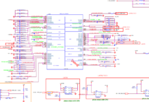
If you are looking for the schematic diagram pdf files of the Inventec Laptop Motherboard, then this article is for you. We collect all the models and give the download links.
Here we have compiled a list of all the available Inventec laptop motherboard schematic diagrams for download. This includes all the popular models such as the Inventec A1300, A1500, A1600, and A1700 series.

Download Inventec Laptop Motherboard Schematic Diagram PDF
| No | File | Download |
|---|---|---|
| 01 | Inventec AEGIS (6050A2416401) Schematics | Download |
| 02 | Inventec CYCLONE DISCRETE (6050A2566401-MB) Schematics | Download |
| 03 | Inventec Everest-M (6050A2447101) Schematics | Download |
| 04 | Inventec Islandpark schematics | Download |
| 05 | Inventec Lepus SODIMM EDP Schematics | Download |
| 06 | Inventec Luxor10fg Schematics | Download |
| 07 | Inventec MW12 Schematics | Download |
| 08 | Inventec ONTARIO-SL (6050A2498201) Schematics | Download |
| 09 | Inventec RALPH1.1 LV1.1_Lauren Schematics | Download |
| 10 | Inventec S18 Schematics | Download |
| 11 | Inventec Topaz 1.1 Schematics | Download |
| 12 | Inventec VV10AD2 Valima Schematics | Download |
| 13 | Inventec VV10AU2 Valima Schematics | Download |
| 14 | Inventec W14 Schematics | Download |
What is a Schematic Diagram?
A schematic diagram is a drawing that shows the electrical connections and components of a circuit or system. Schematic diagrams are often used in electrical engineering and electronics to describe how a circuit works.
Inventec laptop motherboard schematic diagrams can be found in the Inventec service manual for your specific model. These manuals can be found on the Inventec website or from your laptop’s manufacturer.
How to Read A Schematic Diagram
When trying to repair or rework an Inventec laptop motherboard, it is important to have a clear and legible schematic diagram. The following guide will help you read and understand an Inventec laptop motherboard schematic diagram.
The first thing to note about an Inventec laptop motherboard schematic diagram is the different colors that are used. Each color represents a different component or connection type. For example, red typically represents power, while blue represents data.
The next thing to note is the different symbols that are used on the diagram. These symbols represent different components, such as resistors, capacitors, and transistors. By understanding the meaning of these symbols, you can better understand the function of each component on the motherboard.
Finally, it is important to take note of the numbered labels on the left and right sides of the diagram. These numbers correspond to specific points on the motherboard, making it easier to identify where each component is located.


